 |
RC Helicopter Set-up by HollyHeli (John Wilson) |
|
RC Helicopter Set-up by HollyHeli (John Wilson) |
Regular Checks
There are essential pre- and post-flight ground checks on RC models, just like on full-size aircraft, that should always be made. When it's a maiden flight, or changes have been made, there are additional checks (next paragraph). Here are the essential ones:
1. Correct model selected on (computer) Tx.
2. Appropriate switch positions set
(especially throttle hold,
flight mode &
throttle stick).
3. Blades straight, blade fixing bolts secure but not over-tight
(see here), blade
grips secure.
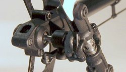
4. Head free to rotate, tail belt drive OK.
5. Tx on, aerial (antenna) extended if 35MHz.
6. Power Rx, wait for Rx happy (no flashing lights),
gyro initialised and working.
7. Move sticks and confirm correct tail pitch response and swash movement.
8. Range check.
9. If necessary switch gyro mode.
10. Throttle hold off, or initialise ESC if necessary.
11. Spool up, check for any funny noises or odd responses, if necessary re-set
flight mode.
12. Take-off & hover, gently check control responses & trim.
13. Post-flight, throttle hold/cut on, set flight mode to
normal.
Additional Checks
The additional checks will include some or all of these, depending on what you've been up to:
A. Re-set any altered Tx settings from set-up to flight appropriate.
B. All ball links are secure.
C. Rudder & gyro response is in correct direction (these are independent).
D. If using an auto-stabilsation device, check responses are in the correct directions.
E. Set gyro gain to an intermediate value.
F. Zero trims (other than rudder trim if set to null out drift in HH).
G. Spool up carefully on turntable to double-check gyro, adjust gain if badly out.
H. Measure head speed on ground in idle up mode (80% to 90% throttle, 0 deg pitch).
Take care.
I. Look for vibrations or noises that might suggest imbalances.
J. Adjust main blade tracking.
K. Set gyro gain on ground following flight testing. Re-test etc.
L. Optimise throttle curves, advanced flyers may measure head speed in flight and log
electrical parameters.
M. Feel battery, ESC and motor temperature after flight (disconnect
flight battery before handling motor).
A fair number of the above are not actually set-up activities, but many are an essential part of every ground test or test flight. Some of the specific set-up tasks require further detail and will be covered in the remaining sub-sections.
You can find some additional notes by ChopperAddict here:
Preparing a new helicopter for it's first flight
How (virtually) ALL R/C helicopters should be armed
Checking out your new helicopter - things to look out for
Before flying, particularly after messing with gyros and Tx settings, it's nice to double check the gyro function and roughly set the gyro gain. A turntable with a non-slip surface can be helpful, even if you haven't got fixings to clamp the heli to it.
Tail Checks
If the gyro is incorrectly orientated or (if it has one) the reversing switch is wrongly set (it isn't obvious because sometimes 'reversed' can be correct and 'normal' the wrong way round) you can get a nasty surprise, because instead of providing 'negative feedback' and opposing the main rotor torque, the tail will aid and abet the torque reaction. If the heli is on a surface that provides the skids with grip, the first indication, when you spool up, is when the heli leaps around and tries to swipe you with the tail rotor (don't ask how I know, I was a raw 'newbie' and too close, my only heli injury to date, a minor cut thankfully).
If the rudder function is reversed as well, it's even worse because if you have time to react (you probably wont), you'll make things even worse. If the gyro is right, but the rudder wrong (this is quite possible since the gyro reversing and rudder channel reversing are separate, independent, functions) the heli wont spin around suddenly, but it will be awfully confusing to fly. Having said that, I gather that some people do 'fly the tail', most however want a clockwise (from above) turn to the starboard when they give right rudder on the Tx and vice versa for port.
These days, after working on tail related parts of a heli, I check both tail rotor control direction and gyro response before even connecting the flight battery! Then I double check (very carefully) after connecting it, prior to spooling up the first time on a turntable. This provides a third check and may even allow some initial gyro gain adjustment if there is too little or too much response (see later). Here's what to look for to check correct rudder control and gyro operation.
Most RC helis have clockwise rotating main blades and (certainly Align ones) work this way around. If you give left rudder, the rudder servo should push the tail pitch control rod toward the tail and the pitch slider should move away from the bearing assembly (toward the rotor). If you rotate the tail so that one blade points up and one down (i.e. 90 deg to the boom), the top tail blade, viewed from above, should change pitch anticlockwise (counter clockwise) looking down on it. This final check must apply to all helis with clockwise rotating main rotors, regardless of the tail slider mechanics, because the tail blades (which always rotate up into the main rotor wash) must decrease in pitch to cause the nose to turn to port. Obviously, if you give right rudder, things happen in the opposite direction.
If the response to the rudder stick (whilst the heli is sitting completely still) is the opposite of the above, you will have to reverse the tail servo response, either by flicking the reversing switch on a simple Tx, or by reversing the Ch 4 setting on the channel reversing menu of a computer radio. Do not also reverse Ch 5 unless you want to separately alter the direction of the switch you may have assigned to gyro mode (rate/HH). Don't forget to check that the tail response is now correct.
The left rudder response described above is the same reaction that you want (automatically) from the gyro if the heli tries, unbidden, to make a starboard turn or right-hand piro. To test the gyro, set it in rate mode and turn the heli sharply clockwise (looking down on it). The tail pitch servo horn should twitch backward toward the tail. This can be a bit hard to see, so (if you can) put it in HH mode and turn the heli nose right, perhaps more gently, the servo horn should move backward and more or less stay there. It might return part-way to centre when you stop moving the heli, but that doesn't matter, it's the initial reaction that counts.
If the gyro response is the wrong way around, turn off the power to the heli and move the little reversing switch on the gyro body to the opposite setting (using a non-aggressive plastic screwdriver). Then, check that the gyro response is now correct and just double check that the tail response to the stick is also still correct (I'm fairly convinced that there are no gyros out there that reverse the pilot input as well as the gyro response, but I may be wrong!).
Gyro Settings
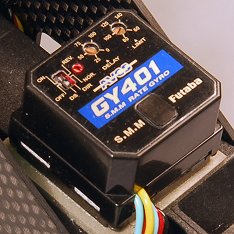
If there is very little, or no, response from the gyro, you may need to up the gyro gain. If the control channel (usually Ch 5) is not connected (or there isn't a wire, see Section 5), the gain setting is done using the trim screw on the gyro. Always use a small enough plastic screwdriver (often provided) to avoid chewing up the adjuster and be gentle. Only set the gain about half-way. When I talk about gyro gain, I'm only talking about what you set on a Tx menu. In fact, the 'real' gain may depend on other factors, but I wont get into that.
Setting up gyro gain on the Tx is a confusing area for recommendations, because different Txs use different conventions. Many computer Txs have a bar graph to show channel output state. It usually goes from say +140 to -140 and for Ch 2, for instance, 0 is centre stick. Sometimes the numbers vary. I think the extra 40 in this example is to allow for full trim either way. I'll assume that Ch 5 is for the control connection, but any other spare channel will work the same. Obviously there are no trims for Ch 5 because it will be associated with a toggle switch, not a Tx stick and the end point settings (usually 100% by default) set the range. With gyros, settings on Ch 5 will usually give rate mode in one direction and HH mode in the other. For instance, on Futaba, the higher the upper end point setting, the higher the gyro HH or AVCS mode gyro sensitivity. If you go negative by increasing the lower end point, the higher will be the gyro rate mode sensitivity. The centre ('zero') setting will effectively switch off the gyro.
It gets worse! Although you can allocate a switch to Ch 5 and set up 'positve' and 'negative' end points to assign gyro gain in each mode, many Txs also have a customised gyro menu. Often, this goes from 0% to 100% and allows two settings, one for each switch position. If you set 50%, the gyro gain is zero. If you go positive, it increases, so at 50% + 50% = 100%, we have maximum HH mode gain. However, if we want, say 60% HH mode gain, we would need 50% + (60%/2) = 50% + 30% = 80% because there is only a range of 50% available to each mode. Conversely, if we wanted say 64% gain in rate mode, we would have to set the 'normal' mode gain to 50% - 32% = 18% (so less is more!).
Some manufacturers (Futaba is one) try to make this clearer by providing an alternative gyro setting menu page which automatically does this arithmetic, so you can directly enter 60% in AVCS gain and 64% in 'normal', thus saving getting a headache. If you have a computer Tx, it's well worth trying to bottom this out using the manual.
At the end of the day, the gyro settings have to be checked on the heli. It will be obvious if the rate and HH settings are reversed, for instance, if you play with the gain settings and twiddle the heli around by hand. Before trying to fly, we want middle-of-the-road gyro gains to avoid early disaster and this is where a turntable can help out.
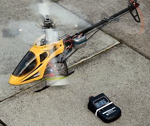
Turntable Test
If a turntable isn't available, try to first spool up the heli with the skids on a shiny surface, such as a piece of smooth cushion floor (lino to you oldies). Stand well back! Start in rate mode and set the gain to around 60%. This might equate to 30% or even 20% (50% - 30%) depending on your Tx and gyro (see above).
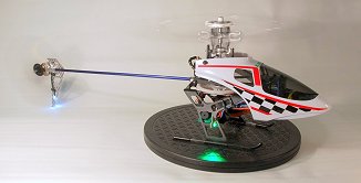
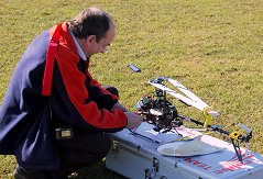
I use a very simple procedure for checking rudder and gyro function, having picked up a modelers' turntable at a RC boaters' trade fair (I think they use them to put things on for painting etc.). The bearings were a bit stiff, so I sprayed some silicone lubricant into it, however, a bit of resistance isn't a bad thing because it stops wild oscillations when the rotor starts turning. Generally there is enough friction between the skids and the ribbed plastic turntable surface, though I have to be careful not to let the heli drift off the thing, when it gets light on the skids. I would normally do the turntable testing out of doors; the action shot above was made with great care using a small heli at low RPM (no pilots or photographers were harmed in the making of this tutorial!).
Any gyro or rudder reversal will be very obvious using a device like this. The rudder servo position can be set, as described in Section 6, in rate mode (having first nulled out any gyro drift in HH mode with the Tx rudder trim), so that the heli does not spin around with the rudder stick central (also see 'Set up the initial tail servo position on the boom correctly'). The gyro gain can be increased, if the tail does not seem to be holding positively, but don't overdo this because too high a setting can cause violent tail wag in flight, which might be masked when the heli is still on the turntable. It will probably be necessary to fine tune the servo position and gyro gain in hover.
Although the head speed should be reasonably predictable from the calculation described in Section 7, it is nice to confirm it and maybe 'tweak' the throttle curve a little. I have developed a cheap, simple and safe way of measuring the head speed (main blade rotation rate in RPM) on the ground.
Any cheap aircraft prop tachometer can be used. Mine is a 'Supertacho' made for J Perkins Distribution, bought for the princely sum of £21.99. These have a light sensitive resistance element (photo resistor) as a sensor that detects the flicker when a blade passes between it and a light source. For this reason, they often cannot be used in artificial light (particularly neon tubes) because they will detect the 50Hz mains frequency.
Anyway, it is usually safer to spool up out of doors (you've got more places and further to run – only kidding!). The only problem is that the resistor points forwards (the case is designed to be hand held, which heli pilots don't want to do) and these units are not very stable stood end-on so that the resistor points upward, under the rotor. A much better method is to mount a small mirror in front of the photo resistor, with the unit lying on its back under the rotor (about two thirds of the blade length out, toward the tip) so the the interrupted sky light is reflected onto the sensor. I use a circular mirror glued onto a flat plastic 'handle' bent at 45 deg. There are little inspection mirrors available that could also be used. I use a rubber band to hold the handle against the back of the tacho; it doesn't matter if it tilts slightly.

These tachos usually have a large lcd display, so you can stand well back and still read them. Make sure the 2 blade setting is selected (unless, unusually, you have more) and don't let the flybar paddle pass over the sensor or you might get a doubled frequency! A true maximum reading can be achieved on the ground by using a throttle and pitch curve that gives the maximum throttle you will have at 0 deg pitch (this is where head overspeeding could occur). Obviously the head speed can be read at negative or positive pitch, but beware of boom strike at extreme negative pitch and inadvertent take-off at positive pitch! The aim is to achieve a target constant head speed whilst flying, which can only be fully checked using a fancy tacho that you look through (while someone else flies, hopefully).
This bit, of course, assumes that you can fly, at least well enough to deal with initial deficiencies in the set-up (that you will be correcting) and to hold a reasonably stable tail-in hover at about chest height. If you cannot do this yet, or probably could but lack the confidence, get a proficient RC heli pilot to help out, at least until the set-up bugs are ironed out. The final adjustments are done by taking off into a stable hover out of ground effect.
We've already covered main blade tracking in Section 9.
Adjust the rudder servo position to achieve a neutral adjustment at mid stick in rate mode.
Increase the gyro gain until the tail starts to wag, then back off slightly. Land to make adjustments. If necessary do this separately for both rate and HH modes.
Set the cyclic trims to achieve a reasonably stable hands-off (briefly) hover. Establish a stable level position before allowing the cyclic to centre for this test. You may prefer to land to make adjustments – be safe not sorry. Do not necessarily try to null out all the drift to the left on take-off, as this aileron trim may not be optimal for hovering out of ground effect or for forward flight.
Gyro function can be checked by hovering tail-in then climbing rapidly (climb-out) by sharply raising the collective (don't make any change in rudder input). Of course, only do this test if you are confident to fly higher and can deal with any yaw that might turn the heli away from tail-in.
In HH, the tail should stay pointing toward you. If it twitches to starboard at the start of the climb, land and increase the gyro gain slightly, but not so much as to induce tail wag (back off from this point). A slight twitch during a violent climb-out might be unavoidable and doesn't matter provided the tail quickly comes back and holds.
In rate mode, if you have a computer radio, you will probably need to activate the REVO mixing and experiment with the revo curve that determines the degree of tail rotor pitch adjustment for any given collective setting. Inhibit this if you switch to HH.
In forward flight (assuming your flying has progressed to this), the heli behaves differently compared to hover, particularly when turning. It may be necessary to review the trim settings achieved in hover, however this is a complex subject that I think I will leave to the experts!
Electrical Performance
Talking of experts, if you really want to know more about the performance of your ESC, motor and battery during flight testing, there is a nifty little device called a 'Watt's Up' (see above). It can be used on the bench, but it's also small and light enough to be installed in a temporary fashion on a 450 or larger size heli to log the electrical performance.
This can help in finalising gearing and pitch/throttle curves to get the best performance without over-taxing the motor, battery or ESC. The picture below shows actual post-flight logged values of watt-hours (Wh), amp-hours (Ah), peak power (Wp), minimum LiPo voltage (Vm) and peak current (Ap) following flight testing of my modified Belt CP with a new Align 430X 4050Kv motor replacing the Esky 3800Kv unit. Although the voltage dipped to 10.43v under load (a safe 3.48v per cell) it is 11.15v with no load, demonstrating how unrepresentative a simple off-load measurement is.
This set-up, with a 10T pinion, gives a head speed in excess of 2600 rpm and flight times up to 9 min with a 2200 mAh LiPo. This flight used 1638 mAh, which is (1638/2200)*100 = 74.5% discharge (within the safe 80% discharge for a LiPo). The motor is rated at 330W/30A and my Castle Creations ESC is rated at 35A continuous, which could be a rather small margin. However, in the test (which included fairly vigourous climb-outs), the current never exceeded 22A or the power 229W, which represents a very safe margin.
Mechanical Performance
We also briefly mentioned dampers in Section 2. Part of advanced set-up is choosing the right grade of damper and this can only be finally checked during flight testing. If you are just learning to hover, a softer grade of rubber is helpful, making the heli more forgiving. Advanced pilots prefer a harder damper to give a sharper, more precise, cyclic response. I also mentioned 'head nodding' caused by too slow a head speed. If a low head speed is desired for learning, substituting soft dampers may cure nodding.
<1 Additional ground (pre-flight) checks are needed after build, replacement or repair.
<2 Rudder and gyro functions are independent and correct direction needs to be checked for both.
<3 Setting Tx gyro gains is confusing! It should be just below the setting that causes tail wag.
<4 A turntable is useful for initial tail and gyro checks.
<5 It is easy to check head speed on the ground, but take care.
<6 If in doubt get help and always land to make Tx adjustments unless you are very experienced.
<< 1 Intro 2 Helis 3 Safety 4 Head 5 Radio 6 Tail 7 Motor 8 Blades 9 Pitch
Go to next section – 11. What on earth does that mean? >
<<< ChopperAddict home <<< GatleyGallery RC Helis
© John E Wilson 2010 with thanks to my friend and colleague Bill Boley for the flight session photos.