 |
RC Helicopter Set-up by HollyHeli (John Wilson) |
|
RC Helicopter Set-up by HollyHeli (John Wilson) |
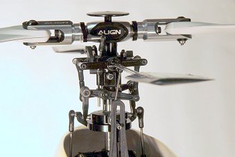
When you assemble a kit, often the first task suggested is assembly of the main rotor head. Even with an ARTF kit, the head might not be set up right.
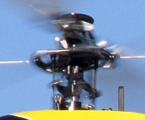
Firstly, what does the head do? Well, obviously, it supports the main rotor blades and rotates them (see above). But it must also transfer all the complex blade pitch changes discussed in Section 2 to the blades, controlling their angle of attack to provide control of lift (in CP helis) and direction (in all fully controllable helis). This is done by means of the swashplate that we have already talked about.
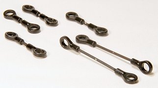
The head also supports the flybar, letting it tilt via a 'see-saw' bearing and a rocking 'cage' (or something similar) and provides mechanical 'mixing' of both the inputs from the pilot (via the swash) and the flybar, by means of several little double ended levers or control arms (supported on off-set bearings) and attached links. The links are assembled from threaded rods with self-tapping plastic ends (ball couplings) installed that snap onto the balls on the swash and at the ends of the levers. These ball joints allow for the slight changes of angle as the links and levers move. To avoid confusion, note that when I talk about 'links', I usually mean the whole assembly (the threaded rod and the self-tapping plastic ball coupling ends). They say that 'one picture is worth 1000 words'.
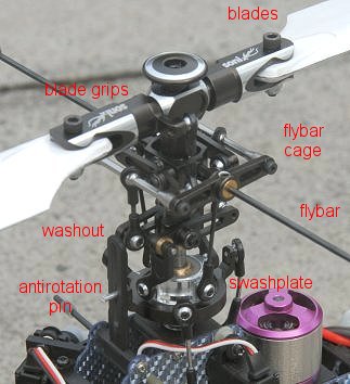
The swashplate is supported and driven by (usually) three servo links connecting to the non-rotating lower part; an antirotation pin prevents it turning but allows it to tilt and go up and down (in a CP heli). The vertical movement allows a full range of pitch adjustment from extreme negative to extreme positive. The rotating upper part of the swash is usually linked to an intermediate assembly oddly known as the 'washout' (there must be a reason, but it's far from obvious!) by two hinged links on the short end of a lever. The washout assembly (that rotates with the head) is kept in alignment by two guide pins which allow it to slide up and down at a fixed distance from the swashplate. When the swash goes up, in most designs, the blade pitch goes more positive.
There are some simplified CP heads that omit the washout assembly and they work in the opposite direction (when the swash goes up the blade pitch goes more negative) because the extra levers on the washout reverse the action. FP heads don't usually have a washout assembly either.
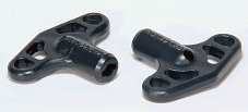
The upper swash is also linked to the long ends of the control levers attached to the flybar 'see-saw'. Just to make things more complicated, the long ends of the washout levers are similarly linked to the flybar cage. Finally, the short ends of the control levers (mounted on the see-saw) link to the blade grip control levers. These usually provide 'trailing edge control' i.e. the links are on the blade trailing edge side of the grips.
Usually, a head is built from the top down; blade grips, links, flybar cage, links, washout assembly, links, swashplate, servo links. If you have bought a pre-assembled head (particularly an Esky one), or are assembling one from parts, read this. Some final set-up is needed once the head is mounted on the heli and the servo and radio set-up is complete (see Section 5), but the following set-up with the head off the heli is a good start.
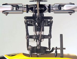
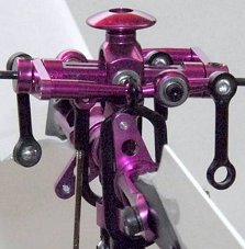
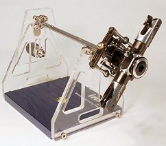
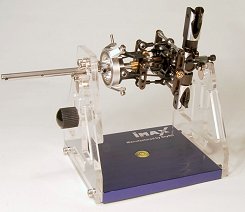
Note that in the left hand picture the flybar is tilted up to show the head better, so the blades are similarly tilted away from us; they are at 0 deg collectively, however. The head on the right, for comparison, is in need of attention and should not be flown.
Bear in mind that the end result needs to fulfill just four simple criteria.
The blade grips need to both be aligned exactly (initial, static, tracking adjustment) when at 0 deg. That means that when the blades are fitted they are both completely horizontal i.e. the blade fixing bolts are both exactly vertical (all this assumes the main shaft is vertical).
When the blade grips are at 0 deg, the flybar cage and the four lever arms on the washout should be horizontal and/or lined up (main shaft vertical).
When installed on the heli, the swashplate should have full and equal movement above and below the 0 deg blade pitch position (see 'here)'.
The swashplate should be level (at right angles to the main shaft) when the cyclic is neutral (cyclic servos centered).
This section will concentrate on just the first two points. So, how do we achieve them? Well, by making the links that connect between the various balls on the rotor head assembly the correct lengths. This is done by choosing the right length link rods and screwing the plastic ball coupling ends onto the threaded rods until the right length is achieved.
This is specified either as the exposed length of rod remaining, the overall length or as the distance desired between the balls. Decent kits, like Align, have good manuals that specify the dimensions, that will get you close. This is where the caliper gauge and/or ball link gauge comes in useful. If there is no manual, it's a little harder, but not much.
Try to screw the plastic ball couplings onto the threaded link rod symmetrically (i.e. the same depth of thread should be left showing both ends). If the whole of the rod is threaded, mark the middle with a dot of ink, paint or 'snowpake' to assist in this. This will avoid the couplings coming loose (not good).
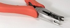
Ball link tools and possibly pliers are useful (but try not to mangle the threaded rods, protect them from the pliers with cork, card or rubber if you have to use them).
Note that most plastic ball couplings have an easy pop-on side that should always be offered up to the ball when snapping on the link. This minimises the stretching of the coupling, which, if made loose or cracked by abuse, might seek revenge by popping off in flight. This always happens in the middle of a violent and challenging maneuver, or at high altitude (or both).
With Align kits, the 'A' on the plastic coupling should face away from the ball. If they aren't marked, check them with a magnifier and look for a slight chamfer onto the rounded inner edge. If you really can't tell, push them very gently each way round and if nothing happens, keep alternating, gradually increasing the force applied until the link snaps on. It should be possible to do this with fingers and thumb, but if the coupling is really stiff, the end forks of the ball link pliers can be used (very carefully – don't scratch the ball). Always use ball link pliers to remove links (using the inner part). The 'rivet' goes on the ball and the fork opposite pulls off the plastic link. If the link refuses to snap off, do not just use more force, reseat the pliers and try again gently until it pops off. Just one extra thing - you guessed - don't scratch the ball.
If the plastic links are too stiff on the balls, replace them, or use a ball link sizer to very carefully shave off some plastic. The technique for this is covered in one of Finless Bob's video tutorials. The links should not flop around, they should support their own weight – just. A heli with stiff links is more difficult to fly, the smaller the heli, the worse the effect. Equally, loose links cause sloppy handling and may come off.
Setting up the links between the blade grips and flybar cage is easy, because the distance between the cage and the blade grip assembly is fixed. All you have to do is make sure the grips are at 0 deg when the lever arms and cage are horizontal (main shaft vertical). With flat topped blade Align style main blade grips, temporarily removing the 'head stop button' allows you to sight along the tops of the blade grips to get them exactly level. The links should end up the same length.
Fitting links to a head with a flybar cage usually means taking apart the cage to install them then reassembling it. Make sure it is reassembled square and loctite the bolts. On some Align heads there is no real adjustment to these particular links because the ball couplings are screwed on to be touching.
The links to the washout assembly and the swashplate are a little more difficult to size if there is no data. This is because they slide up and down the main shaft and until everything is assembled, its hard to tell if they are at the right height. It may be necessary to re-adjust these links later so that the 0 deg pitch position is in the middle of the travel range and everything is aligned as described above under 'happy rotor'. Again, each pair of matching links should be the same length.
The swash/washout travel range is limited at the top by the guide pin mounting (see above). At the lower extreme, either the washout will run off the antirotation pins, or the swashplate will foul the top of the heli. It should be possible to achieve +/-9 deg., preferably +/-10 or even +/-12 deg to allow a symmetrical idle up pitch curve.
The length of the servo to swashplate links will have to be set later, when the cyclic servos are installed. With the servo centred, the horn should be at right angles to the servo, or in line with it, depending on the servo's orientation in the heli's frame. This is so that the link to the swash is as near to 90 deg to the horn as possible when the head is at 0 deg pitch. Why is this important? Well it looks neater, but the real reason is so that at minimum or maximum pitch, the angle the link makes is still as close to 90 deg as you can get; this will make control easier. The swashplate should be made level (i.e. at right angles to the main shaft) by adjusting the lengths of the three servo links.
Before the swashplate leveling is finalised, it may be necessary to apply electronic sub-trim to get the servo horns truly at right angles. This requires radio set-up, so this will be covered in the next section. This will also allow the pitch range available with the swash travel set up to be checked and modified.
Many people balance blades (that's covered in Section 8), but head balancing is much less popular. This is probably because on small helis it is not terribly important. A well made CNC machined head should be close to perfect. Also, specialist equipment is needed (I do have one balancer that claims to make it possible, statically at least - see below), though a simple jig can be made from a couple of head bearings turned on their side. I've only put these pictures in because they look technical (I've never bothered to do this for real!)
If my rotor head was out of balance I'm not sure what I could do about it anyway! However, if the flybar has been fitted (this isn't shown in the pictures), it can be balanced, assuming the head is already OK. I just do it by measurement.
Firstly, fit the flybar rod and centre it using a caliper gauge. Lock it in place. Then fit the paddles, measuring the distance between their inner edge (or the flybar weight) and the flybar cage – make these distances equal. Any further adjustment, if a balancing method is available, can be done by moving out, slightly, the paddle on the light side. Beware, however, of poor bearings that might render the balancing invalid and make things worse. Don't forget to lightly loctite the paddle or flybar weight fixing (grub) screws.
In addition, check out ChopperAddict's 'Some common causes of Rotor head vibration'.
<1 A CP main rotor head is complicated!
<2 But the main rotor head set-up requirements are relatively straightforward.
<3 Adjust pitch control links so everything in line or horizontal at a blade pitch of 0 deg.
<4 Only snap links onto the balls the right way round.
<5 Balance the flybar (just by measuring lengths), the head is probably OK.
Go to next section – 5. Radio & Servos >
6 Tail 7 Motor 8 Blades 9 Pitch 10 Test 11 Def 12 Stuff >>
<<< ChopperAddict home <<< GatleyGallery RC Helis
© John E Wilson 2009 with thanks to my friend and colleague Bill Boley for the in-flight photo.