 |
RC Helicopter Set-up by HollyHeli (John Wilson) |
|
RC Helicopter Set-up by HollyHeli (John Wilson) |
There are two types of dc electric motor used in RC helis; brushed and brushless. There are also IC engines running on various liquid fuels, which I have no real experience of. Neither have I used gas turbines ('jet engines') that are now available (at a considerable cost!). This section will therefore concentrate on the setting up of electric motors that are rapidly becoming more popular than IC due to their increased performance (largely due to better batteries), clean habits and relatively quiet operation (both with regard to rf interference and noise).
Of the two types; IMHO, for RC helis, brushed motors ('cans'), as they say in the US, suck. This is because they often need running in, are relatively inefficient and lose performance due to brush or commutator wear or contamination and due to magnet deterioration caused by overheating. I have wasted many hours of potential learning time and have confused my lack of flying ability with poor heli performance; all due to brushed main and tail rotor motors (Honey Bee CP2). Now, I think their only place is in very small sub-micro helis and even there, they are rapidly being replaced by 'nano' brushless motors.
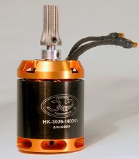
There are only two aspects of motor set-up; mechanical and electrical. Mechanical includes choice of motor, brushed or brushless (outrunner/inrunner), pinion tooth count and mesh. Electrical includes choice of motor (voltage and Kv rating) and (if the ESC requires it) end point set-up on the Tx.
If you buy a RTF, ARTF or kit heli, it probably includes a motor. If it's a brushed one and the heli is 400 size or bigger, bin it and its ESC and get a brushless replacement (you'll need a suitable brushless ESC of slightly higher current rating than the motor's maximum).
Check this cautionary tale regarding fitting motors:
Fitting the motor into your helicopter.
If a brushless motor is included, someone else has chosen the Kv rating. As you may have already found out, this is the speed (RPM) the motor does per volt. The voltage is the LiPo battery voltage. All you need to do is choose the motor pinion tooth count, or accept the one on it, to determine your main rotor head speed.
Very simply, the head speed is determined by [motor Kv rating] x [LiPo voltage] x [(motor pinion teeth)/(main gear teeth)] x [motor & ESC efficiency] x [(throttle %)/100)]
For example, on my Trex 500, this is currently about [1600] x [22.2] x [12/145] x [0.85] x [(80/100)] = 2000 rpm. For more details try the Dark Horse Helicopter Power & Setup Calculator. If you are really keen, try the advanced version of this.
Also, read ChopperAddict's 'The truth about Motor KV, Amps, Watts, RPM, ESC's & LiPo life'.
The desired head speed depends on several factors.
Blades and head. Wood blades shouldn't go much over 2000 rpm (less if long), check with the manufacturer's recommendations. Plastic or carbon reinforced plastic or glass fibre may well be stronger, the best are carbon composite blades. Check with the heli manual and/or blade manufacturer for recommended maximum RPM. Plastic blade grips are less strong than metal ones, so plastic heads should also be speed limited (check on the 'stock' set-up maximum head speed and don't exceed it).
Flight time. To some extent, lower head speed increases flight time, however, more positive pitch is needed, so there may be little or no gain.
Stability. Too low a head speed makes a heli sluggish to control and 'nodding' instability can occur. However, high head speeds can make a heli over-responsive for a beginner and can sound scary.
Performance. Beginners might prefer lower head speeds for hovering practice, more exciting maneuvers benefit from increased head speed.
Head speed should not be reduced, using the Tx programing, by lowering the throttle curve or throttle channel end point, since ESCs run increasingly inefficiently below 100% (aim for normal mode hover at about 80% throttle). If the head speed needs reducing, use a lower tooth count pinion instead.
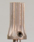
Having chosen a suitable pinion (or not), the motor position needs to be set for correct mesh between the motor pinion (usually brass or steel) and the main gear (usually nylon or some similar plastic). Gear teeth should roll over each other and their shape encourages this, but they must only overlap by 2/3 to 3/4 of the tooth depth. If they are too tightly pressed together there will be friction and accelerated wear. However, if they are too loosely meshed, there is a danger of damaging the plastic gear due to jumping or stripping teeth.
Some people suggest setting the motor position and tightening the motor bolts whilst pressing the gears together with a piece of paper between the teeth – obviously the paper is later removed! This is OK if the paper is of suitable weight and bendyness. I prefer to rock the main gear while holding the pinion to determine the right motor position for a good mesh. You should hear a clicking sound and feel some 'play', but too much movement is bad. Few gears are perfectly round, so there should still be some 'play' at the tightest point. If there is too much at the loose position, get a better quality gear!
Sometimes gears do not mesh well. Brass Esky 9T (9 tooth) pinions wear very rapidly because there is a mis-match in tooth pitch with the main gear, 10T or bigger are better. Consider this if choosing the motor Kv rating for a desired head speed. With larger motors, steel pinions could be a better choice.
On medium size (500) to large (600) helis, loctite the motor bolts once the position is established. Remove and replace them one at a time, so as not to lose the setting, but be prepared to have to make a small readjusment since the motor sometimes pivots on the remaining bolt even when it's tight. Opinion is divided as to whether it is wise or necessary to loctite grub screws, such as those securing the pinion to the motor shaft. Some say that they will be impossible to remove; I've always found blue Loctite OK with grub screws.
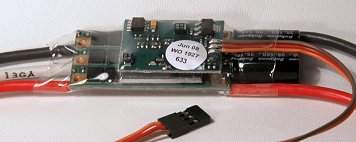
Nearly all ESCs can be programmed to some degree. The simplest are set up using the throttle stick on the Tx, more sophisticated ones use a programming card or a USB PC interface and software (see below), but can sometimes be set up just using the Tx.
To program an ESC using the Tx, you have to enter a programing mode. This is almost always done by turning on the Tx, raising the throttle stick to 100% (fully up) and then connecting the ESC to the main flight battery (usually a LiPo). This is not normal safety behaviour, so it is probably a good idea to un-mesh the motor or remove the blades as discussed in Section 3. The ESC communicates to you via sets of bleeps, which actually come from it vibrating the motor, which doubles as a loudspeaker! Just follow the instructions.
Typical ESC settings include:
Brake
This
is for powered gliders with folding props and has no place on a
heli, leave it off. ChopperAddict provides the following tip:
Correctly set the Brake to OFF on the ESKY stock ESC (V1 or V2).
Battery type and/or voltage
Some ESCs automatically detect number of
cells, sometimes it's safer to tell them. Don't exceed the ESC's
maximum voltage.
Battery protection cut-off voltage and type
LiPos
can self-destruct (sometimes dramatically) if over-discharged,
which is why different voltage cut-offs can be set on the ESC. But
It's is embarrassing to have the motor suddenly stop on a heli, so
there is usually a soft-cut-off or pulsed power mode, which you
should select. Choice of cut-off voltage depends on flying style
and battery characteristics (how much the voltage 'sags' under load
toward the end of its safe discharge cycle). LiPos should not be
discharged to below 20% of full capacity (80% discharge) and/ or 3v
per cell unloaded. Between 3.3v to 3.5v is good for an on-load warning level if
you also have an on-board LiPo alarm, the ESC cut-off may be set
lower. Really energetic flyers don't like cut-offs and use
flight timers instead (or set the cut-off to a voltage below 3v per
cell, which might be OK on load as long as the unloaded voltage
returns to 3v or above). It's best to set an alarm to a high value
(say 3.5v per cell), then progressively reduce it when you see how
much charge you have to put back into the battery. The ESC cut-off
can then be set a bit below the alarm voltage. If you rely solely
on the ESC cut-off or timer, use the same principle, slowly
increasing flight times and/or reducing ESC cut-off level, checking
the battery discharge each flight.
Reversing
If the motor runs backwards your heli might fly unpredictably. To keep
the nice matching coloured wire connections(a brushless motor can be
reversed by swapping any pair of its three wires) you can reverse
it using this ESC setting.
Spool-up rate (soft start)
Just as a safety
feature, this is useful. It also stops the heli jumping around when
the motor starts abruptly and can save your main gear teeth. Set a
value that gives a smooth spool-up but doesn't take so long that you
take off before achieving the programmed head speed. However,
beware, if you are practicing
autorotations
using the throttle hold
and want to be able to 'bale out' by
bringing up the throttle; you may need to defeat or at least
drastically reduce the slow spool setting. Some ESCs have a setting
that overrides the slow spool-up provided the throttle hold is set
slightly above 0%.
Throttle Response
This allows you to change the speed with which the
motor responds to throttle changes. Unless expert, follow the
advice in the heli, ESC or motor manual, or if they give none,
leave it at the default . Sometimes this is the high
speed setting, but be aware that in some circumstances (fast
spool-up?) this setting could be hazardous to your main gear teeth
or even your battery.
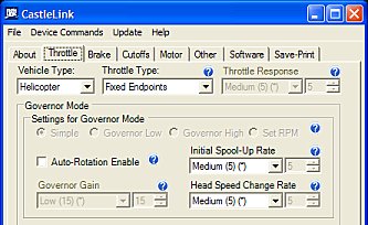
Governor mode
This is clever stuff that maintains a predefined head
speed without you having to fiddle around with the throttle curve to
compensate for pitch changes. Follow the manual if you want to use
it, but note that (allegedly) some ESCs don't do a very good job.
Timing
Brushless
motors receive precisely timed pulses to their windings to make them
go. You can optimise these for particular types of motor and/or
trade performance and efficiency. If in doubt leave this at the
default setting for your type of motor unless you know better.
BEC voltage
The Battery Eliminator Circuit is often built into the ESC to provide
power for the Rx, gyro
and servos and can sometimes be set to
different voltages (often 5v, 5.5v and 6v). Beware, some servos and
gyros are designed for 4.8v. You can get away with 5v, but 6v
may fry them (see this).
However, the servos might work better at 6v.
You can use a 5v regulator on the fussy components (some cameras
might also prefer 5v). If you have too many servos, more than one
digital servo, or higher LiPo voltages, the ESC's BEC might struggle
to provide the peak current required. Check the specs and if in
doubt, get a separate BEC that can deliver. Be careful not to
duplicate power connections with separate BECs, many require that
you disconnect the red wire on the throttle channel connection from
the Rx (but this is going beyond mere set-up...).
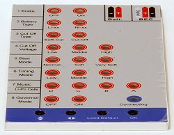
Here is a typical programing card that connects to the ESC throttle channel for setting a very similar set of parameters to the ones listed above (I didn't mention the music option!).
The final ESC set-up job is to either teach it the throttle end points (0% and 100%) or set them on the Tx since not all Tx, Rx and ESC set-ups use the same standard pulse timings. Futaba use a reversed convention, but this should already have been allowed for in the Tx reversing settings.
Many ESCs (e.g. Align) learn the 100% setting when you switch on in programing mode with the throttle set high. They then learn the low throttle setting when you lower it to 0% preparatory to doing the other settings. Some, however (e.g. Castle Creations (CC)) don't learn either throttle extreme. It doesn't mean they are bad ESCs, you just have to do a little more work and not everyone (including me) immediately realises that. The heli will probably fly with the throttle end points set to their default 100% settings, but your throttle curve may not be as planned. When I first used a CC 35A ESC on my Belt CP, the soft start was far from soft and often tried to topple the heli over as the blades started to move. Once they were spinning everything seemed OK. Since converting the Belt to DTS and replacing the Esky head and tail with Sonix mechanics, I discovered the need to set-up the end points and the start-up is now silky smooth (it also flies 1000% better without the purple stuff and all the indirect linkages). If your ESC uses a PC interface, make sure that the 'fixed'endpoints' option is selected.
Here's how you do the throttle set-up. First, as instructed in Section 3, disengage the motor pinion from the main drive gear and re-tighten the mounting bolts enough to hold it securely away from mesh. If possible, set up the slowest spool-up rate on the ESC. If you are worried about running the motor flat out without any load on it, read Section 3 first (under 'When You Have to Connect the LiPo... ').
If necessary, first select 'fixed throttle end points' on the ESC set-up. The motor start and full throttle points that the ESC 'sees' will then be determined by the end point settings on your Tx. You can adjust the throttle end points on your Tx to get the full stick throttle range (but end points vary with different makes and models of Tx). In most cases, zero throttle (needed to allow ESC arming) will be at a lower end point setting, according to CC, of around 10% to 20% and the ESC will reach full throttle at a higher end point setting of 75% to 85%. The settings on my Futaba 9C Tx for 25A and 35A CC ESCs seem a bit different to this, 97% & 108% and 92% & 110% respectively. Perhaps Futaba counts differently, as the default is 100% on both upper and lower end points.
So, first set up a linear throttle 'curve' on your Tx (i.e. 0%, 25%, 50%, 75%, 100%), this will ensure that you are using the full throttle range make the end point settings more accurate. You may wish to use a spare idle up flight mode to avoid disturbing your normal flight mode throttle curve, which shouldn't be linear. If you use all the idle up modes for flying, don't forget to reset the throttle curve after calibrating the throttle end points. Then, go to the travel adjust or end points menu on the Tx. First set both throttle end points (Ch1 or Ch3 depending on Tx manufacturer) to around 50%. Then connect the flight battery to the heli. The ESC will probably not arm (often shows a flashing red LED) but treat the heli with care as if the ESC had armed.
Put the throttle/collective stick at its lowest position. Some people also lower the throttle trim to zero. This is OK on a simple Tx that doesn't have 'digital trims' and makes sure that the 0% throttle position is physically obvious on the Tx and is easily reset if the trim is accidentally bumped. However, on some computer Tx lowering the digital trim below its middle position can mess up your throttle curves – I've stopped doing this and leave the digital trim at its mid position – the ESC set-up (automatic, or manual as described here), will forthwith recognise this as 0%.
Next, reduce the lower end point on the Tx until the ESC just arms (bleeps, light may go out). This often means increasing the % figure for the low stick end point. This is, of course, with the stick already in its lowest position. Some people reduce the lower end point (increase the %) by 2% or 3% (but no more) below this setting, to ensure reliable arming.
Now raise the throttle/collective and beware, the motor will start. Take the throttle/collective stick up to its highest position, then increase the upper end point on the Tx until the ESC is just seeing full throttle (usually a solid red LED means full throttle on the ESC). Again, some people also increase the setting by 2% or 3% (but no more) above the point where the full power ESC light just comes on, to ensure they have 100% power just before hitting the throttle stop. Note that with Futaba, the low stick end point is the second (right hand figure) and the high stick end point is the first (left hand figure) because the throttle channel works in reverse.
This procedure gives you a full throttle range on your Tx which assures that your throttle percentages will be correct.
ChopperAddict provides some tips specific to the Spektrum DX6i Tx:
Ensure the throttle is set correctly with a DX6i.
See also:
How to check that your brand new ESKY Radio & ESC is working correctly.
and
Reset the throttle trimmer correctly on Esky 0406 Transmitters.
Last time I looked, there was an excellent article on setting up the throttle channel and ESC at:
www.modelairplanenews.com/Media/MediaManager/TotalControl.pdf
<1 Brushless is better!
<2 Don't overspeed blades, particularly woodies, or plastic heads
<3 Choose the motor and pinion to determine head speed, don't just use the Tx settings.
<4 The main gear-to-pinion mesh needs to be not too loose, nor too tight, but 'just right'.
<5 ESCs need to be set for helis, they're programmed by the Tx (beeps), a card or PC interface.
<6 To get best performance you might have to set the throttle end points on your Tx.
<< 1 Intro 2 Helis 3 Safety 4 Head 5 Radio 6 Tail
Go to next section – 8. Blade balancing & CoG >
9 Pitch 10 Test 11 Def 12 Stuff >>
<<< ChopperAddict home <<< GatleyGallery RC Helis
© John E Wilson 2009.