 |
RC Helicopter Set-up by HollyHeli (John Wilson) |
|
RC Helicopter Set-up by HollyHeli (John Wilson) |
For main blades, the simple answer is yes, balance them (or at least check 'em), but there are some exceptions and tail rotor blades also need some consideration (although I'll leave them until later).
The rotor head and blades need to be symmetrical and balanced to avoid the assembly wobbling and vibrating when turning. Whilst blades out of the packet are often quite well matched, especially the better carbon fibre ones, we are talking about tiny differences (sometimes less than 0.1g and fractions of a mm) that are magnified when blades are turning at 2000 to 3000rpm. This may all seem very obvious, but it is slightly less obvious what we have to do to get our blade balance spot on.
First we need to understand some physics, I'll keep it very simple!
To achieve a smooth rotation with no sideways forces, the CoG of the rotor blade and head assembly must be at the exact centre (axis) of the main shaft. In case you got bogged down with the physics definition after following the link: the CoG is the point through which the total weight of the object acts, its 'balancing point'.
If the CoG of the blades and head assembly doesn't coincide (align) exactly with the centre of rotation, there will be a reaction force on the heli because the CoG is moving in a little circle when the main rotor shaft rotates. The head and blade assembly would much rather be rotating about its CoG than the shaft. When this happens, the whole mass of the rotating blade assembly is being pulled around in the horizontal plane rather than just being rotated and this force reacts on the heli, which, because it hasn't got infinite mass and isn't completely rigid, will move around (vibrate). The higher the head speed, the larger this force will be and the worse and more rapid the vibrations, which will also resonate with the helis natural modes of vibration, amplifying the whole effect. None of this is good for the structure, bearings, electronics (particularly gyros) nor flight stability.
So what causes this to shift in the CoG away from the geometric centre of the assembly? Well, if one blade weighs more than the other, everything else being equal, the CoG of the head assembly will be slightly shifted toward the heavier blade. This is the same, whether the head is static or rotating and the difference can be detected by separately weighing each blade or by bolting both onto a simple 'prop balancer' or beam type blade balancer. This is called 'static balancing'.
However, this is not the whole story. The blades could be exactly the same weight, but their individual CoGs could be at slightly different points along their length. Consider the converse case where both blades happened to have the CoG at exactly the same distance from the fixing point at the root, but have slightly different weights acting through those points. Most people correct the 'static balance' using bits of tape on the blades. On a balancer, it might seem that less tape can be used to correct the light blade if it's added at the end of a blade. In actual fact, the saving is negligible! More importantly, the CoGs were right before the tape was added, but now the CoG of the light blade will have been moved slightly outward toward the tip. But this is not apparent whilst the blades are static – they balance perfectly now! However, when they are attached to the heli and spun up, the combined CoG will have been slightly displaced from the geometric centre, so the 'dynamic balance' is now wrong and this might be noticeable in terms of vibration.
In practice, usually both the weight and the CoG of each blade will be slightly different, but how much matters? Well, I don't bother balancing the little plastic or fibre blades on my sub-micro FP helis. The blades are not very long and don't spin very fast. However, on a 450 size, the head speed is considerable and static balance should be checked. If the blades are good quality, their CoGs should be pretty close. If the static balance needs correcting, tape should be added at the lighter blade's CoG so as not to upset the dynamic balance, which is probably near enough.
With the bigger blades that go on a 500, 600 or 700 size heli, it is worth checking the dynamic balance too, because any inequalities will be magnified due to the larger radius of the longer blades. Here's how to do it, you don't need to have the blades on the heli for any of this.
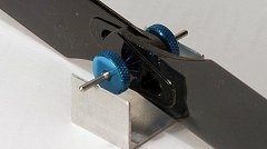
For dynamic balancing, we need to either compare or measure and mark both blades' individual CoG. This can be done with simple improvised equipment. Some people use a spare spindle as a 'knife edge' to balance the blade on, others use one of those fancy metal straight edges with either a triangular cross section or three 'ribs'. The spindle has the advantage that it can be rolled to and fro to determine the tipping point, this is the 'Finless' method. Two blades can be easily compared this way, however, note the need for a 'registration' mark, described below. Make sure that whatever 'knife edge' you use, it only has a a thin line of contact with the blade and is at 90 deg to the blade edges. A cutting mat or ruled paper will help get this alignment right, otherwise the measurement could be off if the blades are skewed.
To compare the CoGs of the two blades it isn't enough just to line up the root or tip and compare the marks. Sometimes the bolting hole at the blade root is not quite in the same position on both blades. What is vital is the distance of the CoG from the exact centre of the blade grip bolt. That's what determines the distance from the head axis to the blade CoG when the blade is bolted on the head and that's what matters for dynamic balance.
In the 'Finless' method, you put a spindle, screwdriver or bolt that is a snug fit through both blade fixing holes and 'scissor' them. You then make a registration mark on both that lines up. This registration mark is subsequently used to align the blades (now parallel) on the 'teeter-totter' spindle so that the blade fixing holes are exactly level with each other. The spindle is rolled back and forth to identify the blade with the lighter tip. Tape is then added to this blade end until the blades tip together. This has the advantage that you don't need to accurately mark the blades' CoG during the dynamic balancing, but you may have to add more tape later to the CoG of one of them, to achieve a static balance.
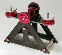
There is a similar method, that I've adopted, which allows one or two other options. In principle this could be done using the simple 'teeter-totter', however I've got a fancy beam type balancer with two thick wires that the blade rests on, that makes marking the CoG a little easier. You move the blade back and forth until the beam is exactly horizontal, just as when balancing two blades. The blade's CoG is where the little pointer that tells you it's in balance lines up. The CoG can be marked on the blade with a fine nibbed marker pen although I often use a tiny triangle of insulating tape that can be moved around. This has the advantage of allowing a contrasting colour to that of the blade. Always choose the leading edge to mark since this is more in line with the blade root fixing hole.
Next, put a spindle that is a snug fit through both blade fixing holes and slightly 'scissor' them. Compare the CoGs. Note which blade has the CoG closer to the root and add a second mark to this blade slightly toward the tip exactly in line with the other blade's CoG. This is the desired CoG for the first blade. If the CoGs exactly coincided straight away congratulate yourself on your choice of blade but, don't erase or remove the mark yet, you may need to add tape there to statically balance the blades. As in the 'Finless' method, tape may be added to the end of the first blade until it CoG coincides with the other blade. However, there are other options, which I will explore after the next sub-section.
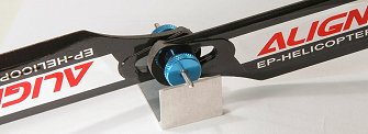
Static balancing should be easier than finding the blade CoG because the two blades joined together have nearly twice the length of one, but, in my experience, it is surprising how many commercially made balancers give inaccurate results. The simplest way to compare two blades is to bolt them together and use the bolt as a pivot. Since a low friction bearing support isn't very easy to arrange, I would suggest buying a simple balancer, like the Align one, that has a spindle, like a 'prop balancer'. I've made mine more accurate by constructing a simple 'knife edge' bearing support for the spindle to roll on, using a small piece of 'U' section aluminium, with the bearing edges filed to a blunt 'knife edge'. This works fine for small blades.
A few words of warning. On any balancer, the blades must be aligned so that the leading or trailing edges are parallel (i.e. so the blades are at exactly 180 deg to each other). If one is crooked, the distance from the balance pivot to the blade's individual CoG will be slightly reduced and it will upset the true balance. Again, the cutting mat or ruled paper (or a table edge) can be brought into service. Also, on the simple balancer with a horizontal pivot, the blades will be turned 90 deg from their position on a heli. There are two ways of mounting them in the balancer. First, mirrored, like on a heli, but with the leading edge up on one and down on the other and second, non-mirrored so both leading edges are either up or down. OK, that's three options really; which is best?
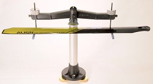
The mirrored arrangement is neutrally aligned with the CoG running through the pivot position and is generally used, but will this give the best test of balance?. With both leading edges facing down, the CoG is above the pivot, whilst this is less stable it might be more sensitive as a teeter-totter method. If both leading edges are facing up the assembly will be more stable and might actually hang in balance once this is achieved. I'm not sure which is best, try experimenting. Sometimes the bench top gets in the way and only allows one option. The alternative is a beam type balancer where the blades are usually in the same orientation as on the heli. I always mount them mirrored on these so that the forces on the balance pivots are equal.

There is one other option. Electronic scales. Some of these are very accurate, even cheap ones can read to 0.1g, but they need to warm up before a stable reading is achieved. I don't rely just on these, but they can provide a useful check on the mechanical balancer.
If the blades are out of balance, we need to add a bit of tape to the lighter one until the blades or balancer stays horizontal. I use different colour plastic insulation tape, or those nice shiny Align adhesive labels. If possible, wrap the tape around the leading edge of the blade. You don't want any edges facing the air steam or the tape might peel off.
There are at least two ways of adding tape to get both static and dynamic balance right. We will assume that some adjustment is needed on both.
The first is quick and easy, but you may end up with more tape than absolutely necessary. OK, we have compared the individual blade CoGs and we know which needs it's CoG moving out toward the blade tip. We can do this by adding tape to the blade near to (but not at) the tip, where the blade is still parallel sided. This will probably make it the heavier blade, so we then add tape to the CoG of the other blade until they balance (weigh the same). If it's still lighter, we add more tape to its (new) CoG. It may be possible to reduce the amount of tape needed, in some cases where the lighter blade has a CoG further out, by putting the tape near the blade root, however, my second method may be preferable once you start to go down this road.
The second method is harder, but is more elegant. The aim is to only add tape to the lighter blade and to align the CoGs at the same time. How do we do that? Basically by trial and error and by adding the tape at any point along the lighter blade. This will only work if the CoGs are not too far out, but with most good quality blades this should be the case. Unlike the 'Finless' method, we could be moving the CoG in, toward the blade root, if the lighter blade has a CoG further out than the heavier blade. To achieve the final balance, measurements of blade balance will have to be alternated with measurement of the lighter blade's CoG, as the amount of tape and its position is established. This could be a bit tedious until you get a 'feel' for how much adjustment is needed.

Check out ChopperAddict's 'How to balance rotor blades with no special equipment' for an alternative take. Also, blades that are too tightly clamped in the blade grips can appear to be unbalanced when you spool them up; they should be tight enough to prevent them 'flopping' around, but no more. Read this.
Most of the stuff in this section so far is aimed at main blade balancing because larger, heavier blades, only slightly out of tolerance, are more likely to cause noticeable vibration problems. However, the same physics applies to tail rotor blades and they do go round a lot faster than the main blades. The effects of imbalance are perhaps more subtle and are more likely to manifest themselves as a rapid vertical shaking of the tail, causing a sort of 'pitch vibration' or cause funny noises.
Single piece tail rotors can be balanced statically using a simple 'prop balancer' provided there is a suitably sized hole in the centre and the balancer bearings are free enough (you can get magnetic ones). Separate blades pose more of a problem since that may not fit a standard balancer, this is where an electronic balance may score, but it would have to be accurate to better than 0.1g. Otherwise, you can improvise and adapt existing balancers. Balancing tail rotors might be more important on really big helis (600 up). To be honest, I've seldom bothered!
Tail vibration isn't necessarily due to the rotor blades, see ChopperAddict's 'Some common causes of Tail/Boom vibration'. Note his comment about not overtightening the tail blade grip screws or bolts and allowing slight 'flop' of the blades in the grips (slightly looser than the main blades). However, don't make them so loose that they can twist in the grips and modify the pitch angle.
Although it may seem a little 'off topic' in this section, I thought I'd deal with airframe CoG while we have the concept of CoG fresh in our minds. This is really part of the 'trimming' adjustments, but it can (and should be) done before flying a model.
Most aircraft ('planks' as well as helis) are easier to control if they are correctly balanced for and aft (all we have to consider here is static balance). In fact slightly nose heavy is preferred by some. The exact CoG to aim for on a 'plane is not always obvious, you may need to ask the designer. With helis, it is always defined by the main rotor shaft.
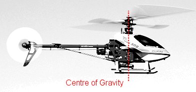
The easy way to check balance is to rotate the blades to be exactly parallel to the boom (fore and aft) and support the heli using the flybar (close to the head so as not to bend it). Fingers will do fine, although some people construct a jig for this. With the heli in flying fettle (battery and canopy on), the skids should be parallel to the ground, or very slightly nose down. The best way to adjust the trim is by moving the main flight battery around, or (in extreme cases) chose a different weight battery. Failing this, at the expense of flight time, weights can be added, but it shouldn't be necessary. Make sure that if you add any additional payloads, such as a camera, the CoG is not significantly out.
There is a less obvious aspect to weight distribution. 3D pilots like to keep the CoG of the heli, in an axial sense, as close to the line of the boom as possible, because this maximises the response in roll and probably helps other maneuvers too. This is why many high performance designs have a high battery tray. However, for beginners, there may be some advantage in keeping the axial or vertical CoG low in order to make hovering more stable. To be honest, I have not noticed much difference (but I'm somewhere in the middle ability range, far short of 3D). My Trex 500 with a high battery position is if anything more stable in hover than my smaller helis with low battery mountings, but of course it's twice the weight of a 450 and has a better power/weight.
<1 Static balance: the blades weigh the same.
<2 The larger the blades, the more carefully they need to be balanced.
<3 Dynamic balance: each blade has its CoG the same distance from the blade grip bolt.
<4 Both static and dynamic balance need to be right to avoid undue vibration.
<5 You can balance tail rotors, but it isn't terribly easy and may not be worthwhile.
<6 Balance the airframe with the battery; the CoG in pitch is where the main rotor shaft is.
<< 1 Intro 2 Helis 3 Safety 4 Head 5 Radio 6 Tail 7 Motor
Go to next section – 9. Blade Pitch & Tracking >
<<< ChopperAddict home <<< GatleyGallery RC Helis
© John E Wilson 2009 with thanks to my friend and colleague Bill Boley for the in-flight photo.