 |
RC Helicopter Set-up by HollyHeli (John Wilson) |
|
RC Helicopter Set-up by HollyHeli (John Wilson) |
First, what does main blade pitch adjustment entail? Sections 4 & 5 got us close to having a CP head that is mechanically correct and servos correctly aligned, but the final set-up needs the main blades on and the Tx controlling the pitch servos. Make sure you have read the safety suggestions in Section 3, you don't want the motor starting unexpectedly because you have to get up close and personal for these settings! Read ChopperAddict's IDLE UP warnings, because you need to use this switch during set-up. The full CP set-up involves ensuring the correct direction and range of pitch control, leveling the swashplate and setting both blades at 0 deg accurately when the swashplate is in the appropriate position.
If you have a FP heli, you don't have to set up the blade pitch, it's done for you. You might have to straighten something out if it gets bent, however!
If you have a RTF CP heli, you shouldn't have to adjust blade pitch, but you might need to; so at least check that the 0 deg pitch setting is correct.
If you have assembled a CP heli you will certainly need to set up the blade pitch by doing all the things in the opening paragraph. This also often applies to ARTF CP helis or if you are replacing the rotor head or upgrading.
If you have a computer radio, you will need to set up or check the pitch range for both collective pitch (where the swashplate moves up and down) and for the elevator and aileron (pitch and roll) cyclic pitch (where the swashplate tilts).
If you put new blades on, you need to check that 0 deg pitch is still correct and adjust it if necessary.
If you have had a crash you need to check that 0 deg pitch is still correct, or replace the feathering shaft/servos/links and do what ever is necessary from the stuff in the first paragraph (after correcting any mechanical alignment tasks that need redoing (see Section 4).
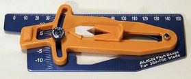
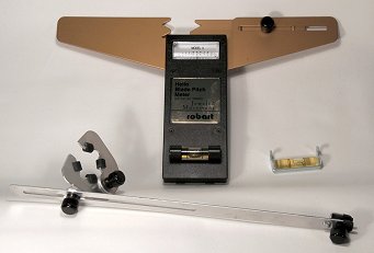
It's no good just 'eyeballing' the blades and trying to estimate the angle, you will get it wrong by several degrees. That much is the difference between flying and remaining on the ground. The only thing you might be able to judge accurately (if they are flat topped) is the initial blade grip 0 deg alignment mentioned in Section 4. We are surprisingly good at aligning straight lines and flat surfaces by eye. Unfortunately, blades viewed end-on are curved. There is, however, a natty device called a pitch gauge that allows us to compare straight lines.
Simple pitch gauges are a bit like the old school protractors that 'old gits' like me (and perhaps some of you) still remember, but with a moving bit (that can be clamped) that indicates a positive or negative angle (they usually span +/- 15 deg). If you have a small heli, get the largest pitch gauge that is still suitable for the small blades, it'll be more accurate than a small one. If you have a medium to large heli, make sure that the gauge will accept the blade width without straining the little springs that locate it firmly and precisely onto the blade.
To measure the current blade angle, you loosen the clamp and slide the moving bit, which has the 'V' shaped sprung guides to locate it accurately on the blade, to near the root (holding the guides clear of the blade to avoid scraping it). Don't run off the parallel part of the blade onto the angled trailing edge, leave a centimeter or so spare. You then line the straight bit up with the flybar and read off the angle. If you want to set up the pitch to 0 deg, clamp the gauge at this setting, then adjust the pitch links until the straight bit lines up with the flybar.
Most heads have a bit of 'slop' caused by the slight flexing of the control arms and the additive effect of 'play' in bearings, bushes and ball links. The worse this is, the worse the heli will be to control (small Esky heli like the CP2 and to a lesser extent the King are particularly susceptible). It will also be much harder to set up and check the blade pitch angles. However, even a good head will allow you to slightly rock the flybar whilst the blade is held in the gauge. If the slop is minor (particularly if you will be using 'idle up'), take an average by rocking the flybar and align the gauge so that it is parallel to the flybar at the centre of the flybar's range of movement. If there is a lot of slop, preferably get a better head or a larger heli! If this is not an option and you are more concerned with hovering than inverted flight, work out which way the blades will be pushed by the air when they are at a positive pitch angle. Hold the flybar, then press against the blades as if you were the air while you set the 0 deg angle. By doing this you remove the 'lost motion' that could reduce your positive pitch setting. If you want equal positive an negative pitch control on a 'sloppy' head, you might need to increase the total pitch range by several degrees more than the nominal 18 – 22 deg you are aiming for.
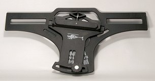
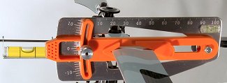
You can get fancy pitch gauges that allow you to clamp the flybar using a bubble level to get it horizontal. The gauge hangs from the blade and a scale on this dangly bit gives the pitch angle. There is an animation of it in use further down the page under 'Collective Chat'.
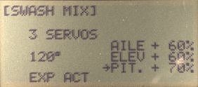
Before finally setting the blade pitch, we need to set the swashplate height correctly and level it. This is done by adjusting the lengths of the cyclic servo to swashplate links. With the cyclic trims set to zero, power the Rx but not the motor and set up the Tx as described in the next section. Move the collective up and down between 0% and 100% and adjust the three cyclic servo pitch links so that the maximum movement of the swashplate is possible above and below the centre stick position. As we agreed in Section 4, the swash/washout travel range is limited at the top by the guide pin mounting. At this extreme, at least 9 deg of positive pitch on the blade grips should be available, preferably 10 to 12 deg. At the lower extreme, either the washout will run off the antirotation pins, or the swashplate will foul the top of the heli. A little extra space is required to allow the swashplate to tilt at least 6 deg in any direction, without fouling, when cyclic input applied. It should be possible to achieve -9 deg., preferably -10 or even -12 deg to allow a symmetrical idle up pitch curve. To get this full movement of the swash, you may need to increase the PIT setting in the SWASH or SWASH MIX Tx menu. The swashplate should be levelled either by eye or using a 'swash leveling' tool. Check out ChopperAddict's hints on 'A quick way to set the height of the swash plate initially'.
For setting up 0 deg pitch on the heli, on the Tx we need a linear pitch 'curve' that goes from 0% to 100%, passing through 50%. Idle up or idle-2 often use this, however, for a neat tip, go to 'How to set up a DX6i easily to do the pitch setup without changing your T/P curves'. On a simple Tx, just switch to idle up (make sure the motor can't run). Check that the cyclic (right-hand stick) trims are still centred (but, on a computer Tx, leave the sub-trims as they are if these have been used to set the servo horns exactly right – see Section 5). Set mid left-hand stick (throttle/collective). On a computer radio, check on the pitch curve graph display that you are accurately at 50% unless you are using the 0%, 50%, 50%, 50%, 100% curve suggested in the tip, in which case anywhere near centre will do. With the Rx and servos only powered, mechanically set the blades to 0 deg using the pitch gauge as described above.
The pitch links that attach directly to the main blade grips provide the 'course' adjustment. Hopefully these are about right if you set up 0 deg by sighting along the blade grips accurately. If the blades are badly out of adjustment you may need to alter these links, try to keep them the same length.
On a Bell-Hiller CP head, the 'fine' pitch adjustment (which is also used for the tracking adjustment described below) is done by adjusting the long links between the swashplate and the flybar cage (or equivalent). These control blade pitch indirectly and are mixed with the flybar input. The adjustment is finer because of the lever function of the mixing arms.
When you make adjustments to the links, treat them with respect and they will reward you. If you bend them or damage the ball links, they will punish you. Always use ball link pliers to remove links. If you are lengthening a link, try to unscrew each ends alternately, so as not to leave too little thread engaged at one end and always put the links back on the correct way round (see Section 4). This means that adjustments have to be made in full, not half turns. Usually this is OK, particularly on the lower pitch adjustment, which is more gradual due to being 'geared down' by the mixing arm lever function.
After all the fiddly mechanical set-up of a head, I always enjoy dialling in the numbers on the radio that control the pitch set-up and it's easy to put right if you get it wrong and easy to change the way the heli responds (well, that's why computer radios are 'cool').
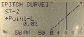
For checking (and adjusting) collective pitch range (swash vertical travel), first select a linear pitch 'curve' that goes from 0% to 100%, as you did when setting the 0 deg pitch. Move the collective to 0% and measure the blade pitch. Move it to 100% and measure the blade pitch. The range needs to be between 18 deg and 22 deg. (i.e. +/- 9 to +/- 11 deg); set this using PIT in the SWASH MIX/AFR menu (see Section 5).
If the swashplate cannot move freely to its extremes (and still allow full cyclic adjustment – see next), or is not centred at 0 deg pitch, make mechanical adjustments to the control links. Unfortunately, to change the range of swash movement and maintain the 0 deg pitch setting at the middle of this range, you may have to adjust all of the links below the level of the blade grip links :>((.
Now check or adjust your pitch curves by switching flight modes and measuring the pitch angle at low collective for each one. There's more on this below. Don't forget the throttle hold, which has its own curve.
For checking (or adjusting) the cyclic pitch angle range (swash tilt), hold the cyclic stick against its springs at its extreme forward and backward pitch positions with one hand, the flybar with your second hand and with your third hand measure the pitch. This is where the fancy pitch gauge with the dangly bit makes life easier! You will probably want about 6 deg of fore-aft blade pitch angle in each direction (12 deg total pitch change) and this should be exactly the same for cyclic roll (bank).
These cyclic throws are set using AILE and ELEV (which should be identical) in the SWASH MIX/AFR menu. If the heli seems too responsive, you can either add exponential (EXP) on the Tx (see Section 5) or reduce the SWASH MIX/AFR setting. However, if you restrict the range of cyclic pitch too much it will make it hard to recover from mistakes, so the EXP option is better. Energetic flyers might want to increase the setting to 8 or more degrees, but beware of mechanical fouling when combining full cyclic at the extremes of the collective. With 11 deg + 6 deg, you already have 17 deg of blade pitch!
As I have already said, the collective pitch range needs to be between 18 deg and 22 deg. (i.e. +/- 9 to +/- 11 deg). This can be reduced using different pitch 'curves' if you have a computer radio, so achieving the maximum practicable range during mechanical set-up allows more freedom later on. While learning to hover, you may set a pitch curve to give a range from -2 deg to +9 deg. Hard core 3Ders would probably like -12 deg to +12 deg.
A common misconception is that the % numbers defining Tx pitch curves give you a predictable pitch range on any heli. Not so! Every setup is unique. The range of pitch control between 0% and 100% on the Tx pitch 'curve' depends on the mechanics of the head, the throw of the servos, the servo horn lengths and the PIT value set in the swash mixing menu. Section 5 gives typical pitch curve examples for hover, sport and 3D flight, but these will almost certainly need to be 'tweaked' for your heli.
The only true test of pitch is a pitch gauge. If you cannot achieve the desired range using the Tx settings, you may have to alter the mechanics, however, try to keep the servo to swash links as parallel to the main shaft as possible (and at 90 deg to the servo horns when centred). This makes the pitch control more linear. It is also good to only use linear pitch 'curves'. The effect of the collective will then be progressive and predictable (unless the motor 'bogs' under load and the head speed is not maintained). The throttle curve should provide more power at high pitch angles to prevent the head speed dropping under load. This will be discussed more in the Section 10.
All the stuff in this section so far can be done on the bench. So, if pitch set-up is done carefully and the Tx pitch curves verified using the pitch gauge, why can't we just reconnect the motor and/or flight battery and fly?
Well, we could, but two things are almost certain to need adjusting: the main blade tracking and the tail rotor/gyro settings. We may also want to check the head speed and tweak the throttle curves.
We'll deal with most of these in the next section on test flying, but tracking is so closely related to main blade pitch adjustment that we will polish it off now.
Please remind yourself of the safety issues involved (Section 3) when you spool up a heli with the blades on for set-up. Some people check the tracking with the heli still on the ground, light on the skids; some clamp it to the bench or to a turntable. Some fly in a low hover (eye level) and some actually hold the heli in front of them and spool it up. The last method is very dangerous and qualifies you for a 'Darwin Award'.
Which of the remaining sensible methods is best? Strapping the heli down is safer for you as long as it is properly secured, not just by the skids, which might rip off and you keep well back (don't forget eye protection). However, beware of resonances causing the heli to shake when it is restrained, you may need a compliant fixing method. The other problem is ground effect. The blades may not track the same as when up high because of the rotor downwash causing turbulence when it meets the ground. Some ingenious people construct tripod arrangements with very small support platforms to hold the heli higher, if combined with a turntable bearing, this also makes the tail rotor adjustments more representative of free flight.
I tend to do the tracking adjustments with the heli untethered, but you must be very careful and be able to hold a stable hover at eye level. When the heli is spooling up on the ground it is subject to ground effect and will not have full hover pitch, so this is only useful to spot gross mistracking. Once the heli is hovering out of ground effect, the tracking test becomes completely valid, but be very careful not to fly the heli any closer than you normally would consider just safe and don't let it drift toward you because you are looking at the blades instead of the fuselage.
You could be lucky, spool up the heli and see the blades in perfect shape, or not. For maximum efficiency and smooth flying, the two blades must rotate in precisely the same vertical plane and you can recognise this in an eye-level hover (but not too close!) of a well set up heli. You see the 'rotor disk' but are not aware that there are two blades. Often, however, one blade 'disc' appears to be slightly higher than the other, diverging toward the tip. Why is this, if the blade pitches were set equal during static bench set-up? Well, one blade, in the dynamic (rotating) situation, must be generating slightly more lift and bending and/or flapping higher due to the greater air pressure on it.
The solution? Make a small pitch adjustment, that's all that is available, but it will work. We could make trial and error adjustments, but this is a bad idea for two reasons. First, it will take longer than determining which blade to adjust. Second, if we adjust both blades, we will lose our 0 deg pitch 'datum'. It is very easy to 'chase' the final tracking setting and increase or decrease the pitch of both blades.
There is an easy solution to determining which blade is high and which is low. Tracking tape – usually available in bright, sometimes almost 'day-glo' colours.
Put different coloured strips toward the end of each blade, wrapping a bit around the leading edge so it doesn't come off. Use equal size strips at the same distance from each blade tip to maintain the blade balance. Out of track blades look like this: >< and provided you can see the colours when the blades are rotating, it is now obvious which blade is higher. Sometimes it is easier to see the colours against black carbon fibre blades, however, many blades are light coloured, this is where the 'day-glo' ones are good.
Assign one blade the status of 'datum' (it doesn't matter which) and don't alter its pitch. Always adjust the other blade and make small changes, one full rotation of the pitch link at a time, using the lower (swash to flybar ) link only. It's a good idea to mark the datum blade and its blade grip so that if you remove the blades, you can replace them the same. We want to get from >< to ----.
With a good quality head on a 450 or larger heli, you should be able to get to almost perfect tracking that stays that way (provided you don't crash or bend the links). Some cheap (usually plastic) heads are virtually impossible to track and you may have to accept a small residual difference in level, which probably will vary due to slop and sticking anyway. When packing up, try to turn off the heli near to 0 deg pitch so that when you fold the blades back you can fit the blade support/holder without putting force on the links and servos.
For ChopperAddict's take on tracking go to: Track the main blades.
<1 With CP helis it's hard to avoid having to adjust main blade pitch.
<2 You must have a pitch gauge and learn to use it (measure blade angle relative to the flybar).
<3 Zero Tx cyclic trims, use a fully symmetrical idle up pitch curve, set 0 deg at 50% collective.
<4 Adjust the blade holder links (course) if necessary, then the swash to flybar links (fine).
<5 Set the collective pitch range and maximum cyclic tilt using the Tx swash mixing.
<6 Be very careful when doing the tracking adjustments.
<< 1 Intro 2 Helis 3 Safety 4 Head 5 Radio 6 Tail 7 Motor 8 Blades
Go to next section – 10. Test Flying >
<<< ChopperAddict home <<< GatleyGallery RC Helis
© John E Wilson 2010 with thanks to my friend and colleague Bill Boley for the in-flight photos.